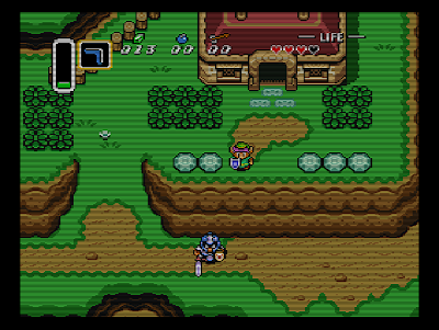
Most of you have probably used an emulator before. And the image probably looked something like this:
This probably doesn't resemble what you remember at all. The reasons for these are several(and some have good reasons) for this post i will focus on explaining how the image should look like.
The image above is only the part of the image that actually has an image in it, the console/pcb actually renders a bigger image.
Vertically the image is actually 243 lines high instead of the 224 in the image above. The console/pcb renders the missing 19 lines as black.
Horizontally it actually takes more time to draw the line that there are pixels in the image. In the case of the snes its actually 282 pixels, 26 more than the 256 in the image above.
So the uncropped image would look like this:
This still doesn't resemble the image you remember, and its probably a good thing that the emulator crops the black bars(which in this form are pretty useless).
*I will refer to snes for the rest of this article but you can replace the word snes with any system*
The snes outputs a 99% valid NTSC broadcast signal. This is an interlaced image at 60 frames per second. Each frame contains the data as show in image 2.
The snes is kind of cheating and creating a progressive image on a interlaced display. It does this by display both interlaced frames as the same frame. NTSC has an ODD and an EVEN frame, together these form a single image at 30fps. What the snes does is display ALL off its 60 frames as an ODD frame basically doubling the framerate to 60fps.
This means that the EVEN frame is never used and that its scanlines remain black. The image in the NTSC frame looks like this:
You're probably wondering why the image looks so wide, this can be explained by:
We know that the image part of a scanline lasts about 52us, we also know that the snes pixelclock runs at a certain speed. We can calulate the number of generated pixels with:
(PixelClock)*0.00005266 = (NumberOfGeneratedPixels)
However this has little to do with actual width, to calculate the correct width we have to finish building the image. As said above the snes tricks the interlaced CRT to display a progessive image. Because it does so this also means that the EVEN frame remains black. This basically means that between each colored line there is an empty black line. The real height is then 486 pixels.
The CRT display had a 4:3 picture aspect ratio, to achieve the same we have to calculate the correct width. Height, 486 is the 3, then width is 648, the 4
So the image as seen on tv looks something like this:
But that still does not match the image you where used to seeing. The last thing we're missing is the so called "Kell factor", this effect basically means that the scanline is brightest in the exact middle and gets less bright as it bleeds out to the sides(vertical bleed), Also the factor defines the amount of bleed beyond the border of the scanline.
The last image below has a kell factor of 0.4 applied (60% bleed):
This last image probably resembles the image you remember pretty accurately, if you save it and zoom in you will see the kell factor in full action. This last image is little bit of a cheat though. The image has been altered by blargg's NTSC filter (an important part of accurate CRT image)
I hope its clear now how a CRT displays the images from a console or arcade pcb.


1 opmerking:
Interesting read :)
Een reactie posten